Die Engineeringsoftware für vom Vorprojekt bis zum Detailengineering
Planen Sie schnell und einfach Ihr Projekt. Vom Vorprojekt, über Basic-Engineering, bis hin zum Detail Engineering bietet AXAVIAedb optimale Unterstützung.
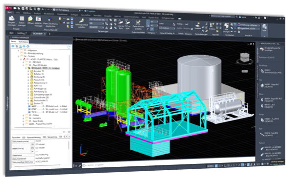
Durch die CAD-Integration wird AXAVIAseries zum durchgängigen Planungswerkzeug. CAD- und Projektierungsdaten fließen zusammen und stehen dynamisch zur Verfügung.
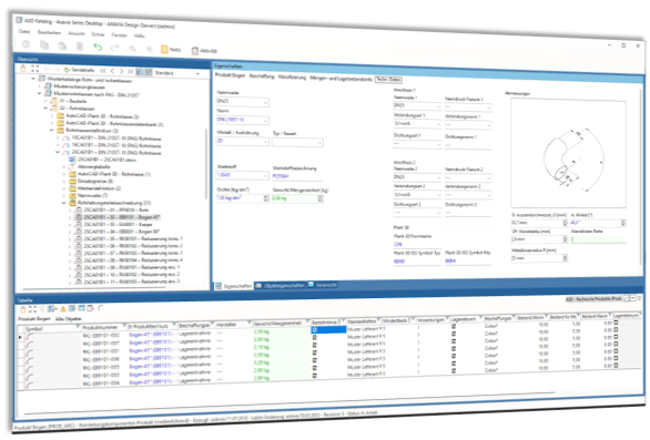
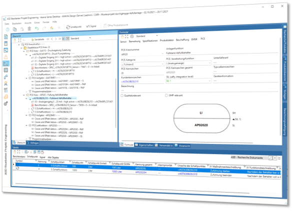
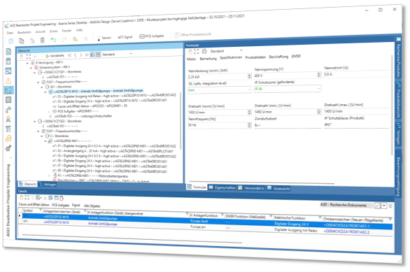
AXAVIAedb stellt ein vordefiniertes Datenmodell für Verfahrenstechnik, Anlagenbau, Elektrotechnik, Automatisierungstechnik und Mechanik in einem erstaunlichen Detaillierungsgrad zur Verfügung. Speziell für den jeweiligen Bereich mitgelieferte Bibliotheken und Berichte schaffen eine Arbeitsumgebung mit hoher Produktivität.
Durch die Engineeringdatenbank haben Sie immer und überall Zugriff auf alle Ihre Engineeringdaten und steigern Ihre Produktivität und Qualität bei Ihren Engineeringprojekten.
Sie wollen Ihre Engineeringprozesse erfolgreich digitalisieren? Erfahren Sie mehr dazu in unserer Modulinformation.
Projekt- und Dokumentenverwaltung für Ihre Engineeringprojekte
Basis der Engineeringdatenbank ist die Projektverwaltung. Organisieren und strukturieren Sie Ihr Engineering in Projekten und schaffen so den nötigen Überblick.
Dokumente sind ein zentraler Bestandteil im Engineering. Verwalten Sie Ihre Dokumente in den Engineeringprojekten und schaffen Sie jedem Beteiligten Zugriff auf die aktuellen Dokumente.
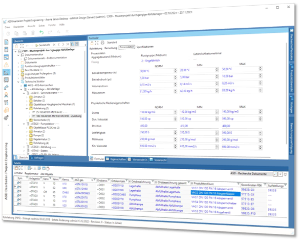
Projektübersicht
Detaillierte technische Struktur
Technische Details
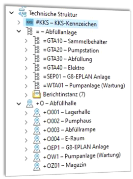
Standardisierte Anlagen- und Ortsstruktur für Ihre Anlagen
Die Anlagenstruktur organisiert und strukturiert eine Anlage nach der Funktion der Anlage. Die Anlagenstruktur wird dabei in den meisten Fällen als Basis für das Kennzeichnungssystem verwendet. Erstellen Sie jede beliebige Anlagenstruktur und definieren Sie so fast jedes beliebige Anlagenkennzeichen, welches in den gewerksspezifischen Bauteilen komplettiert wird.
Neben dem Anlagenkennzeichen wird insbesondere bei großen Anlagen auch eine örtliche Angabe als Bestandteil des Kennzeichnungssystems verwendet. Organisieren Sie Ihre Anlage nach beliebiger Ortsstruktur und nützen diese als Zusatzinformation bei den jeweiligen Komponenten als Ortsangabe.
KKS bzw. RDS-PP Struktur
In Kraftwerken und ähnlichen Anlagen hat sich ein standardisiertes Kennzeichnungssystem des VGB nach KKS bzw. RDS-PP durchgesetzt. Die Engineeringdatenbank erlaubt Ihnen die Möglichkeit Ihr Kennzeichnungssystem nach KKS bzw. RDS-PP aufzubauen. Beachten Sie, dass die KKS bzw. RDS-PP Struktur nicht Bestandteil des Lieferumfanges ist, da diese vom VGB geschützt ist und vom VGB explizit erworben werden muss.
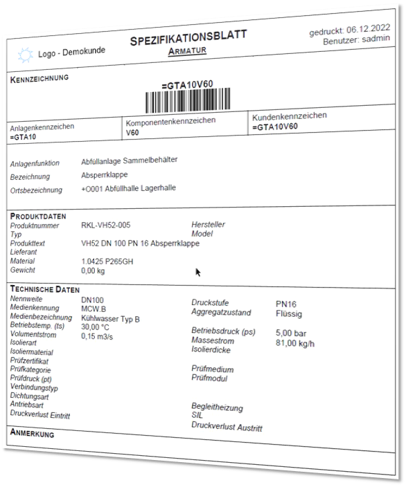
Spezifikationsblätter zur sorgfältigen Dokumentation Ihrer Anlagen
Spezifikationsblätter sind Dokumente, die die technischen Anforderungen und Merkmale eines Produkts oder einer Anlage beschreiben. Sie dienen als Leitfaden für die Entwicklung, Herstellung, Überprüfung und Inbetriebnahme des Produkts oder der Anlage.
Die Spezifikationen umfassen Angaben zu Materialien, Größen, Gewichten, Leistungsmerkmalen, Anschlüssen, Schnittstellen, Sicherheitsanforderungen und anderen relevanten Faktoren. Diese Informationen werden im Engineeringprozess erstellt, um sicherzustellen, dass das Produkt oder die Anlage den Anforderungen entspricht und ordnungsgemäß funktioniert. Die Spezifikationsblätter bieten auch eine Referenz für zukünftige Beschaffungsanfragen, aber auch für Wartungs- und Reparaturarbeiten an der Anlage.
Sie werden als Berichte durch AXAVIA generiert und verwaltet. Der Inhalt entspricht den Informationen der Bauteile.
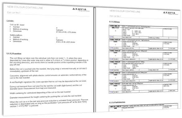
Funktionsbeschreibung Ihrer Anlage
Funktionsbeschreibungen sind ein wichtiger Bestandteil der Dokumentation. Neben einer verbalen Beschreibung sind viele technische Informationen der Komponenten enthalten.
Die Funktionsbeschreibung ist eine Dokumentation der Funktionsweise der Anlage. Dazu wird die Dokumentation in entsprechenden Kapiteln aufgebaut und verbal beschrieben. Für die Einbindung von Bauteilen werden diese mit dem jeweiligen Kapitel verknüpft und in der generierten Dokumentation zusammengeführt.
Die generierte Dokumentation greift immer auf den aktuellen Planungsstand zurück und ist somit immer auf dem aktuellen Stand.
Insbesondere die Unterstützung für die Übersetzung in andere Sprachen ist eine wesentlicher Vorteil für den Anwender.
Alle Ersatzteile im Blick
Eine Ersatzteilliste für den Anlagenbau ist ein Dokument, das eine Aufstellung der Ersatzteile enthält, die für eine bestimmte Anlage erforderlich sind. Es gibt eine Übersicht über die Teile, die regelmäßig ersetzt werden müssen oder im Falle eines Ausfalls schnell zur Verfügung stehen sollten.
Die Liste enthält in der Regel Informationen wie Teilenummer, Beschreibung, Hersteller, Lieferanten und Lagerbestand. Eine solche Liste ist für den Anlagenbetreiber von großer Bedeutung, da sie die Verfügbarkeit und den Bestand der Ersatzteile überwacht und sicherstellt, dass die Anlage jederzeit betriebsbereit ist. Definieren Sie in AXAVIA Ihre Ersatzteile und erstellen so auf Knopfdruck die Ersatzteilliste für die Dokumentation.
Effiziente Beschaffungsprozesse mit Stücklisten
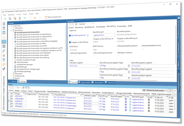
Die Engineeringdatenbank definiert die Stückliste für Ihr Projekt. Die exakte Spezifikation der Bauteile beschreibt jede Komponente im Detail. Diese Stückliste stellt auch die Basis für die Beschaffung dar. Legen Sie fest, welche Bauteile wie beschafft werden müssen (Zukauf, Kundenbeistellung, …). Auf Basis der vorbereiteten Stückliste werden die Daten zur Beschaffung vorbereitet.
Beschaffungstermin
Der Liefertermin wird entweder aus dem Projektmanagement übernommen, oder direkt in der Stückliste hinterlegt. Durch die hinterlegte Beschaffungsdauer wird dann über eine Rückwärtsterminierung ein Beschaffungstermin ermittelt.
Beschaffungsfreigabe
Durch den technischen Verantwortlichen werden die Stücklisteneinträge für die Beschaffung freigegeben.


